Course "Architecture of Multi-Processor Systems"
TP10: Processor Sharing / Task Switching
(franck.wajsburt@…)
A. Objectives
This practical focuses on the mechanisms that allow a processor to operate in multi-tasking mode, i.e. to run several user programs simultaneously. This is done using the technique of time-division multiplexing, where each processor works successively for different programs during time slots of fixed length. The objective of this tutorial is to identify the problems associated with creating, saving and restoring software tasks and to analyse the task switching mechanism in detail.
As we wish to run programs independently of each other, the mechanism allowing to replace one task by another on the same processor must be a "pre-emptive" mechanism, where the task switching is imposed by the operating system, which commandeers the processor, without consulting the running program, and without cooperation from it: Each program therefore behaves as if it has the processor to itself and is unaware that it has only a part of the CPU time and that it shares memory and peripherals with other programs.
Although this technique of "virtualising" the processor was initially developed for single-processor computers, it is also useful for multi-processor architectures. In particular, it allows the execution of cooperative multi-tasking parallel applications with a number of tasks larger than the number of processors in the machine.
B. Hardware architecture
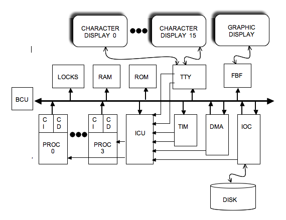
We use a different hardware platform than the generic one used in the previous tutorials. Like the previous one, this architecture contains a variable number of MIPS32 processors, as well as the peripherals you already know, but each processor can execute up to 4 tasks in parallel, which complicates the management of peripherals.
In the previous tutorials, there was only one task per processor, and a TTY terminal was therefore identified by the processor number. As we want each task to have its own TTY terminal, we need a maximum of 16 TTY terminals (4 tasks * 4 processors), and the TTY controller therefore has 16 channels. This requires 16 interrupt lines, for a platform with 4 processors.
Each task (and therefore each terminal) is identified by a double index (p, k), where p is the processor number, and k is the task number on the processor. The global index of a task task_id, which is also the terminal index, is calculated as follows:
task_id = p * 4 + k
For other devices, there is only one disk controller in the architecture, but each processor has its own TIMER and DMA channel. The TIMER and DMA components therefore each have 4 channels.
The interrupt lines will need to be wired to the ICU controller as follows:
- 4 interrupt lines from the DMA controller: irq_in[8] to irq_in[11]
- 4 interrupt lines from the TIMER controller: irq_in[12] to irq_in[15]
- 16 interrupt lines from the TTY controller: irq_in[16] to irq_in[31]
The archive multi_tp10.tgz contains the files you will need. Create a working directory tp10, and unpack the archive into this directory. In addition to the files tp10_top.cpp, and tp10.desc, you will find as usual the embedded software in the soft directory.
Question B1: Complete the file tp10_top.cpp to wire the interrupts on the ICU component as described above. Caution: the 32 ports p_irq_in[i] must be connected, and the unused ports must be connected to a signal which always has the value false.
C. Execution context of a task
The complete execution context of a task is defined by the values of the processor's internal registers, and the values stored in its seg_stack execution stack, the code defined in its seg_code segment, and the global data stored in its seg_data segment.
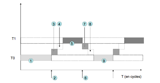
Question C1: Recall the principle of pseudo-parallelism by time multiplexing on a single processor. What is the event that causes the tasks to switch? Use the timeline below to explain the different stages of the task switching mechanism. Hint: You can follow the function calls from the execution of the ISR _isr_switch (in the file giet_2011/sys/irq_handler.c).
The answer to the following three questions is in the file giet/sys/ctx_handler.c.
Question C2: Where is the context of a task saved? Why is it not necessary to save the values stored in the stack when performing a context switch?
Question C3 The GIET uses a static policy of assigning tasks to processors. This means that there is no migration of tasks, and that a particular task will always run on the same processor. How does the GIET remember the placement of tasks (identified by their global task_id index) on the processors?
Question C4: For each processor, it is the operating system that controls the scheduling between the tasks assigned to that processor. How does the GIET remember which task is running on each processor at a given time?
Question C5: Which of the 32 general purpose registers on the MIPS32 processor do not need to be saved during a context switch? Among the system registers, justify why it is essential to save SR, EPC, CR?
Analyse the code of the _task_switch function found in the file giet/sys/giet.s to answer the following questions.
Question C6: What are the arguments to this function? How does the function get its arguments? What is its return value?
Question C7: The _task_switch function is split into two parts. What are we trying to do in each of these two parts? What registers is this function allowed to change in the context saving phase of the outgoing task?
Question C8 Why is the _task_switch function which performs context switching (and which is found in all multi-tasking operating systems) always written in assembly langage?
Question C9: At what address does the _task_switch function branch when it returns to the calling function? Why must the cell containing the $31 register of the context array of a task be initialized (before it starts its execution)? What value should this box 31 of the context array contain?
Question C10 The _task_switch function is called by the _ctx_switch function. This _ctx_switch function is in charge of choosing the incoming task, which implies the definition of a scheduling policy between the tasks. What is the scheduling policy implemented by the _ctx_switch function?
D. Creating and launching tasks
The GIET is not a real operating system. It does not provide a "dynamic" task creation service (i.e. creating a new process, while the machine is already running). GIET uses a "static" creation mechanism where tasks are created once and for all by the boot code. This static technique is often used in embedded applications where the number of tasks does not vary over time.
As in the previous practicals, the boot code can access the entry points of the tasks through the jump table at the beginning of the "seg_data" segment. These entry points are arranged in this table in the order in which the functions with the ((constructor)) attribute were compiled.
The general ideas are as follows:
- At startup, all processors execute the same boot code, but this execution depends on the value of the proc_id.
- By convention, the first task executed on the processor (p) is the task T(p, 0). The other tasks T(p, k), with non-zero k, will be launched later when the timer associated with processor (p) triggers a context switch. It is therefore necessary to treat the T(p, 0) task and the T(p, k) task differently when k is non-zero.
To assign the tasks to the processors and launch the execution, the boot code must initialise different arrays:
- The _current_task_array[NB_PROCS] array defining the local index of the running task does not need to be initialized, since the first task that starts executing on processor (p) is task T(p, 0).
- The array _task_number_array[NB_PROCS], which contains the number of tasks assigned to each processor must be initialized. This number must not be greater than 4.
- The array _task_context_array[NB_PROCS * NB_MAXTASKS] must be initialized for all tasksT(p, k), when k is different from 0, because it is necessary to define the initial values of some registers for the tasks that do not start immediately.
For this purpose the boot code constructs and uses an intermediate array (not used later by the GIET) tasks_entry_point[NB_PROCS * 4], which is indexed by the global task number task_id, and contains the address of the entry point of the task (in practice, it is one of the addresses defined at the beginning of the seg_data segment. This task_entry_point table is different from the jump table at the beginning of the seg_data segment, as it is common for several tasks to execute the same code and therefore branch to the same address.
Question D1: For each processor (p), what are the 3 registers that must be initialized before launching the execution of the task T(p, 0)? What values must they take? Check your answers by comparing with what is done in the reset.s file.
Question D2: For each of the tasks T(p, k), with k non-zero, what are the 4 cells of the context array that must necessarily be initialized? What values must they take? Check your answers by comparing with what is done in the file reset.s.
As far as interrupt routing is concerned, we want the following behaviour: each processor receives and processes at least 5 interrupts: 1 interrupt from the TIMER (to trigger context switches) and 4 interrupts from the TTY controller (each task has its own terminal). Processor 0 receives in addition the IOC interrupt and the interrupt corresponding to DMA channel 0 (so 7 interrupts in total).
Question D3: Given the wiring of the interrupts defined in section B, what values must be written in the MASK[0] to MASK[3] registers of the ICU component to carry out the routing defined above? complete the reset.s file accordingly (icu_mask_array)
Each interrupt line has an associated ISR interrupt routine. The 7 ISRs used in this architecture are the following
- _isr_dma : ISR executed when the interrupt comes from the DMA controller
- _isr_ioc : ISR executed when the interrupt comes from the IOC controller
- _isr_switch : ISR executed when the interrupt comes from the TIMER (context switch)
- _isr_tty_get_task0 : ISR executed when the interrupt comes from a TTY associated with a task of index k = 0
- _isr_tty_get_task1 : ISR executed when the interrupt comes from a TTY associated with a task of index k = 1
- _isr_tty_get_task2 : ISR executed when the interrupt comes from a TTY associated with a task of index k = 2
- _isr_tty_get_task3: ISR executed when the interrupt comes from a TTY associated with a task of index k = 3
Question D4: Explain why it is necessary to define 4 different ISRs for the TTY component when we want to be able to execute 4 tasks per processor?
Question D5: How should the interrupt vector be initialized? Complete the reset.s file accordingly.
It is desired that each task T(n, k) has an execution stack with a capacity of 64 Kbytes.
Question D6: Check that the length of the segment seg_stack defined in the file tp10_top.cpp can support the situation where the 4 processors each execute 4 tasks in parallel. To what values should the stack pointer of each task T(n, k) be initialized? Compare the values you propose with those defined in the file reset.s.
Question D7: Why is it the operating system, and not the tasks themselves that decide the periodicity of context switches (i.e. the value of the TICK). Complete the reset.s file, so that the period is equal to 10000 cycles, and to activate the timer.
E. Multi-tasking on a single processor
The soft directory contains three software applications already used in the previous tutorials.
- main_pgcd.c is the interactive program for calculating the PGCD (TP6). It contains a single software task defined by the function pgcd().
- main_display.c is the program for displaying a sequence of images read from the IOC disk on the FBF graphics terminal (TP8). It consists of a single software task defined by the display() function.
- main_fifo.c is the program for transferring data between tasks through a FIFO communication channel (TP9). This program has two parallel and cooperative software tasks, defined by the two functions producer() and consumer().
We will start by running these four tasks in time-division multiplex on a single processor hardware architecture.
The addresses of the four tasks pgcd, display, producer and consumer must be arranged in this order at the beginning of the segment seg_data.
Check in the Makefile provided that these four functions will be compiled in this order.
Question E1: Complete the file reset.s, to place the four tasks on processor 0.
Start the compilation of the embedded software using the Makefile provided, and then start the execution.
./simul.x -NPROCS 1 -DISK images.raw -SNOOP 1
Question E2: Compare the runtime of the display application (when it shares the processor with 3 other tasks), with the runtime you obtained in TP6 (when it was alone using the processor). Why is the ratio not exactly equal to 4?
Question E3: Vary the value of the TICK (period between two TIMER interrupts). What happens when the period is very large (1 million cycles)? What happens when the period is very small (500 cycles)? How do you explain this behaviour?
F. Multi-tasking on multi-processors
We will now use the time-division multiplexing technique on each of the 2 processors of a dual-processor architecture.
Question F1: Modify the reset.s file to place the two tasks pgcd and producer on processor 0, and the two tasks display and consumer on processor 1.
Start the compilation of the embedded software using the Makefile provided, and then start the execution.
./simul.x -NPROCS 2 -DISK images.raw -SNOOP 1
Question F2 What difference in behaviour do you observe between single and dual processor operation?
Task (or process) scheduling is one of the main functions of an operating system (along with protecting access to shared resources such as peripherals, and managing virtual memory). Since the GIET is not a real operating system, the scheduling performed by the _ctx_switch function is very simple: each task allocated to a processor runs in turn for a fixed time.
Question F3: What criticisms can be made of this GIET scheduling policy?
Question F4: Use the different software applications from TPs 6 to 9 to launch 16 tasks (cooperative or not) on a 4 processor architecture. The reset.s file must be modified to place the 16 tasks on the 4 processors. Compile and run...
G. Report
The answers to the above questions must be written in a text editor and this report must be handed in at the beginning of the next lab session. Similarly, the simulator will be checked at the beginning of the next week's lab session.