Course "Architecture of Multi-Processor Systems"
TP5 : Bus sharing in multi-processor architectures
(pirouz.bazargan-sabet@…)
A. Objectives
In this practical, we are interested in the performance problems posed by the sharing of the bus between processors. When the number of processors connected to the bus is increased, the bus becomes a bottleneck, because the "bandwidth" of the bus (maximum number of bytes transferred per unit of time) is limited. The waiting time to access the bus can become very long when the number of processors becomes large: the consequence is that each processor spends more time blocked waiting for the bus than executing instructions...
In this practical, we use a generic architecture, defined in the files tp5_top.cpp and tp5.desc, where we can vary the number of processors, thanks to the parameter NPROCS on the command line. We also take the opportunity to introduce in the architecture various peripherals which will be used in this and the following tutorials.
B. Hardware architecture
The archive multi_tp5.tgz contains the files you will need. Create a working directory tp5, and unpack the archive into this directory. In addition to the files tp5_top.cpp, and tp5.desc, you will find the application software in the soft directory as usual.
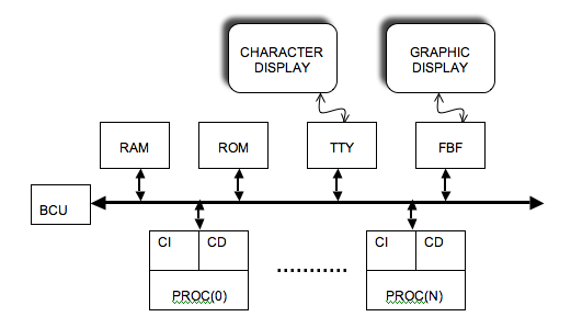
Each processor has its own TTY terminal. So we have several screen/keyboard terminals but only one controller connected to the bus. The memory segment associated with the TTY controller therefore contains NPROCS * 16 bytes, since each TTY terminal has 4 addressable registers.
In addition to the boot ROM, RAM, and TTY controller, this tutorial uses a frame buffer controller, which allows images to be displayed on a graphic screen.
This controller allows to control graphic screens of any size, and we will use in this tutorial a small screen allowing to display square images of 256 lines of 256 pixels. Moreover, we will limit ourselves to "grey scale" images, where each pixel is coded on one byte (256 grey levels).
This FBF device contains a memory buffer that can be read or written to. In the case of an image of 64 K pixels (256 lines of 256 pixels), a first buffer of 64 K bytes contains the luminance values of the (256 * 256) pixels of the image (the luminance of the first pixel of the first line is stored on a byte at the base address of the segment, the first pixel of the second line is stored at the base address + 256, etc.). A second buffer of 64 K bytes is used to store the "chrominance" values, but is not used in the case of "greyscale" images. These memory buffers are periodically scanned by an internal controller (at a video rate of 25 frames per second), and the image in the buffer is therefore displayed on the graphics screen every 40 ms.
Question B1: By consulting the header of the file pibus_frame_buffer.h, specify the meaning of the arguments of the constructor of the component PibusFrameBuffer.
Question B2: what is the length of the segment associated with this component ?
In this tutorial, we will use small caches with a capacity of 16 lines of 8 words, with a single level of associativity, i.e. a capacity of 512 bytes for the instruction cache and 512 bytes for the data cache.
Generate the simulator simul.x using the command:
$ soclib-cc -p tp5.desc -t systemcass -o simul.x
C. Compiling the software application
The software application proposed in the file main.c consists in building and displaying an image of 256 lines of 256 pixels. This image is a chessboard of 64 black and white squares. Each square is a 32 * 32 pixel square.
We build this image line by line, using an array of 256 pixels (i.e. 256 bytes), and we use the fb_sync_write() system call to write a complete line of 256 pixels in the frame buffer.
Question C1: Why do you need to use a system call to access (read as well as write) the frame buffer controller? What happens if a user program tries to read or write directly to the Frame Buffer, without using a system call?
Question C2: Why do we prefer to build a complete line in an intermediate array of 256 pixels rather than writing the image directly - pixel by pixel - into the frame buffer?
Question C3: Look at the file stdio.c, and explain the meaning of the three arguments to the system call fb_sync_write(). Complete the main.c file accordingly.
Check that the base addresses of the different segments defined in the seg_ld file are identical to those defined in the tp5_top.cpp file describing the hardware architecture, and launch the compilation of the system software and the application software in the soft directory, using the makefile provided.
D. Characterisation of the software application
The hardware architecture and the PIBUS protocol define 4 types of transactions on the bus:
- IMISS: Burst read of a cache line following a MISS on instruction cache.
- DMISS: Burst read of a cache line following a data cache MISS.
- UNC: Read a word belonging to a non-cacheable segment.
- WRITE: Write a word (to RAM, TTY controller or Frame Buffer)
We will start by characterising the software application by running it on a single processor architecture.
To do this, we will read, when the application ends, the information accumulated in different instrumentation counters existing in the first level cache controller.
Start by running the simulation with no limit on the number of cycles to determine how many cycles are required to display the image. The application will be considered complete when the exit() system call is executed.
Rerun the simulation, imposing the number of cycles to be simulated, and enabling the display of statistics with the command (-STATS) on the command line.
Question D1: What is the number of cycles required to display the image with a single processor. How many instructions were executed to display the image? What is the average number of cycles per instruction (CPI)?
Question D2: What is the percentage of writes out of the total instructions executed? What is the percentage of data reads? What are the miss rates on the instruction cache and the data cache? What is the cost of a miss on the instruction cache? What is the cost of a miss on the data cache? What is the cost of a write to the processor? Recall that the costs are measured in terms of the average number of processor freeze cycles. How do you explain that these costs have non-integer values?
Question D3: Evaluate the number of transactions of each type for this application. What do you notice?
E. Running on multi-processor architecture
We are now interested in a scenario where the software application (image construction and display) is executed - in parallel - by several processors. For this, we will share the work between the processors, using the fact that the different lines of the image can be processed independently of each other: In an architecture containing NPROCS processors, the proc[i] processor takes care of line (k) if (k % NPROCS == i). If we have 2 processors, for example, processor proc[0] processes even rows, and processor proc[1] processes odd rows.
All processors therefore run the same main() program, but the work done depends on the processor number. The processor number is a value that was "wired" at the time of manufacture into the protected register ($15 , 1). This value is not modifiable by the software, but can be read, when the processor is in KERNEL mode, by using the instruction mfc0. In assembler the following instruction copies the protected register ($15 , 1) into the unprotected register ($27):
mfc0 $27, $15, 1
In a C user program, this information can be obtained using the procid() system call.
Question E1: Modify the main loop in the file main.c to share the work between the different processors in the architecture.
The boot code also needs to be changed, as we now have multiple tasks running in parallel, and each task must have its own execution stack. Again, all processors execute the same boot code, but the execution depends on the processor number.
Question E2: Why must the execution stacks of the N programs running on the N processors be strictly disjoint? Modify the file reset.s, to initialize the stack pointer to a value depending on the number of the processor, so that each task has a stack of 64 Kbytes, whatever the number of processors (included between 1 and 8).
With N processors, each processor processes (256 / N) lines instead of 256 lines. Since the N processors work in parallel and independently of each other, the total execution time should be divided by N.
We define the speedup (acceleration linked to parallelization on N processors) as follows:
speedup(N) = Computing time on 1 processor / Computing time on N processors
If speedup(N) = N whatever the value of N, we say that we have a linear speedup.
We will therefore measure the speedup for different hardware architectures with 1 to 8 processors.
Question E3: Give two reasons why the binary code must be recompiled each time the number of processors is changed.
Run the simulation for 1, 2, 4, 6, and 8 processors in succession. You must first modify the value of the NB_PROCS parameter in the config.h file and recompile the software), then use the argument (-NPROCS) on the simulator command line.
Question E4 Fill in the table below, and plot speedup(N) as a function of N.
| 1 proc | 2 procs | 4 procs | 6 procs | 8 procs | |
| cycles | |||||
| speedup |
How do you explain that the speedup is not linear?
F. Evaluation of bus access times
We are trying to verify the hypothesis that it is the saturation of the bus, and more precisely the increase in the access time to the bus, which is responsible for the degradation of performance, when the number of processors increases. To do this, two indicators are available:
- The printStatistics() method associated with the processor makes it possible to measure the average cost of the various types of transaction. This cost is obtained by dividing the total number of processor freeze cycles by the number of events of each type.
- The printStatistics() method associated with the BCU is used to measure, for each master using the bus, the average bus access time, defined as the number of waiting cycles between the activation of the REQ[i] signal (request for access to the bus by the master (i)) and the activation of the GNT[i] signal (bus allocation to the master (i)). This is done by dividing the total number of wait cycles of master (i) by the total number of requests made by master (i).
The simulations for the 5 architectures must therefore be rerun, by activating the -STATS option on the command line, in order to record the costs and the access times to the bus.
question F1 Why is it absolutely necessary to carry out the measurement at the precise moment when the application ends?
Question F2 Fill in the table below, running the program successively on different architectures:
| NPROCS | 1 | 2 | 4 | 6 | 8 |
| IMISS COST | |||||
| DMISS COST | |||||
| WRITE COST | |||||
| ACCESS_TIME | |||||
| CPI |
The previous question must be taken into account, because the execution time of the application depends on the number of processors.
Question F3: Interpret these results. Is the degradation of the CPI value when increasing the number of processors mainly due to the increase in the cost of MISS, or to the increase in the cost of writes?
G. Modelling bus behaviour
The simulations carried out in the previous questions indicate that there is a saturation threshold, beyond which the increase in the number of processors is no longer useful, because of the limited bandwidth of the bus. We will now calculate "theoretically" (i.e. without simulation) the value of this saturation threshold.
Question G1: Using your understanding of the PIBUS protocol, calculate the number of bus occupancy cycles for each of the 4 transaction types. Caution: do not count the waiting time to access the bus, because the REQ->GNT phase does not use the bus and takes place during the end of the previous transaction. On the other hand, an additional cycle corresponding to the "dead cycle" between two transactions must be counted.
Question G2: Using the results of part D (percentage of hidden reads, percentage of writes, MISS rate on caches, CPI value), calculate the frequency of each of the 4 types of transactions and complete the table below. Since our unit of time is the cycle, these frequencies will be expressed as "number of events per cycle".
| Time_Occupancy | Frequency | |
| IMISS | ||
| DMISS | ||
| UNC | ||
| WRITE |
We recall that for any type of event, the frequency can be calculated as :
(number of events / cycle) = (number of events / instruction) * (number of instructions / cycle)
Question G3: Using the results of the previous two questions, calculate the percentage of the bus bandwidth used by a single processor. Deduce the number of processors beyond which the bus starts to saturate.
H. Report
The answers to the above questions must be written in a text editor and this report must be handed in at the beginning of the next lab session. In the same way, the simulator will be checked (by pairs) at the beginning of the next week's practical session.